
These streams have special requirements due to their highly corrosive and toxic nature. Control of ClO2 gas phase concentrations is essential due to risk of explosion at higher concentrations.
Model C2L15 for 0-15 g.p.l.
Chlorine Dioxide (aqueous)
Model C2G20 for 0-20% v/v
Chlorine Dioxide (gas)
The ClO2 concentration is directly proportional to spectral absorbance at appropriate wavelengths. Our analyzers utilize this principle to continuously monitor the concentration of ClO2 in various liquid and gaseous process streams within the chemical preparation and bleaching system. The sample flows through the spectrophotometer block to provide a continuous readout and electrical signal proportional to ClO2 concentration.
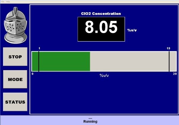
Continuous Readout
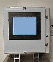
For gaseous ClO2 applications, the sample flows through a sample cell from the upper CPVC bulkhead fitting on the side and exits through the lower CPVC bulkhead fitting on the side. For solution ClO2 applications, entrance into the sample cell is through the lower bulkhead fitting, and exiting at the upper bulkhead fitting.
All the wetted surfaces in the analyzer are of CPVC or Teflon, materials which are chemically inert to ClO2 and halogen solutions. The optical path consists of light passing through an inert sample cell.
After passing through the sample, the light enters a diode array spectrophotometer. This uses certain wavelengths of light for reference and other wavelengths of light for analytical measurement. The quantities of light detected at measurement and reference wavelengths are rapidly determined (milli-seconds timescale). The log ratio of these values is proportional to the concentration of the component being measured. Use of reference wavelengths makes it possible to compensate for some non-analyte sample variability, variation in light source and/or the condition of the sample cell.
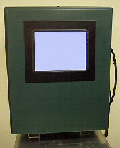
The analyzer is controlled by a small but powerful computer. Electronics are protected by a high quality power conditioning system. Interfacing within the analyzer is via USB standard interfaces. The unit includes analog and digital I/O capabilities, along with a robust set of solid state relays. Electrical power and signal cables enter and exit the analyzer via standard PVC bulkhead connectors on the side of the case.
Control software for these analyzers is proprietary and has been developed in house. It uses data from multiple wavelengths to provide concentration estimates and identify process error states. As such, it provides greater information than is available from single-beam single-wavelength types of analyzer, which is useful in process control and diagnostics. We are able to modify the software to meet specific needs of customers, subject to the cost of these modifications being born by the customers.
Each installation includes three (3) physical copies of the manual, plua a digital version.
On-site training and installation may be available at separate cost, worldwide. Please ask.
Support is available by e-mail, telephone, fax or video conferencing (by appointment).